

Cabling - Part 2
This is the second part of a series of articles on CCTV cabling . If you have not seen the first part , I recommend you to read it before this one, clicking this link: Part 1 - Introduction
Metallic cabling
The most common way to send images from a camera to your destination is through metallic cabling, formed by two cables, one sending the video signal and the other, the return of that signal.
Sending power supply to a camera is also done through a pair of metallic cables.
Electrical equivalent of a cable
Whenever we have a pair of wires running side by side, we have the following electrical equivalent :
Where:
- Rs is the cable resistance, that you can measure with your multimeter in the ohms scale. The longer the cable, the greater the resistance measured. It is usually specified by manufacturers in ohms/km or ohms/100m (ohms/300ft);
- L is the inductance of the cable, specified in mH / m (millihenries) . As the cables are used extended, not in reels, the value of L is practically zero and can be ignored ;
- Rp is the resistance measured between the two cables. It is usually very high, to infinity because between that two cables there is normally insulating material or the air itself. It also can be neglected;
- C is the capacitance measured between the two cables owing to the dielectric (insulating material) between them. The longer the cable the greater is the capacitance. It is usually reported in pF / m (picofarads) .
For practical purposes, let's simplify the circuit, eliminating L and Rp :
Rs resistance reduces video signal level. If a camera sends a video signal of 1 Vpp (Volt peak to peak), can reach only 0.7 Vpp at destination, or even less, depending on the specific cable resistance (ohms / 100m) and length used. Images with levels above 0.5 Vpp are considered acceptable.
Capacitance has a slightly more complex effect.
For a DC voltage, a capacitor behaves like an open circuit, as if he did not exist, because its equivalent resistance is practically infinity. However, for alternating current, a capacitor starts conducting the signal to the ground as the signal frequency increases, as it is in parallel between the two cables. The equivalent resistance of a capacitor or capacitive reactance, as it is called, is also specified in ohms and is calculated as follows:
Xc=1/2πfc
Where
Xc is the capacitive reactance, in ohms;
f is the signal frequency, in Hz;
c is the cable capacitance, in Farads.
Sound confusing? Let's take a practical example :
Suppose a coaxial cable with a 3 ohms/100m resistance and a capacitance of 53 pF/m. So, for a 100m cable length, total resistance would be 3 ohms and capacitance, 530 pF. Using the formula above , we have Xc values as the following table :
Signal frequency (Hz)1001 K10 K100 K1 MCapacitive reactance (Xc) in ohms300 K30 K3 K300302 M3 M4 M5 M6 M15107,5657 M8 M9 M10 M4,293,753,343
Table above shows a very high reactance, 3 Mohms, for a 100 Hz frequency, but it decreases as the frequency increases. For example , for frequencies from 1 MHz and 10 MHz, electrical equivalent of this cable would be:
For 1 MHz, capacitive reactance of the cable is 300 ohms, 100 times greater than the cable resistance. Signal loss that goes to ground through the capacitor is less than 1 %.
But for a 10 MHz frequency , capacitive reactance is 30 ohms, only 10 times greater than the cable resistance. Signal loss that goes to ground through the capacitor is about 10 %, 10 times higher than for the 1 MHz frequency .
But why frequency is important?
Because a video signal is composed by frequencies ranging from 0 to 10 MHz. The higher the camera resolution in horizontal TV lines (HTVL), the greater the bandwidth required :
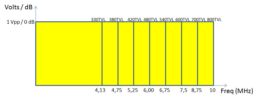
For instance, in the sixties, a television set had only 330 HTVL, occupying only 4.13 MHz of bandwidth; 420 HTVL cameras require 5.25 MHz ; 600 HTVL, 7.5 MHz and so on.
In short, this means that quality of the cable and its length can compromise the performance of a system at high frequencies, damaging the image resolution delivered to the other end. Remember:
NO MATTER WHAT SIGNAL A CAMERA SENDS; WHAT MATTERS IS WHAT IS ARRIVING AT THE OTHER END
For example, if a poor quality cable and/or with excessive length is used, the image of a camera with 800 HTVL resolution could reach its destination with only 400 lines of resolution! All investment in a better camera was useless, wasted on inappropriate and cheap cabling.
Imagine for the given example above, if it was chosen a cable with a 30 Ohm/100 m resistance instead of 3ohms...
Skin effect
That's not only the resistance and capacitance of a cable that affect their performance. There is another factor, the skin effect, which also changes its response at high frequencies.
When submitted to a direct current, this current distribution is uniform across the cross section of the conductor. However, when the cable is submitted to an alternating current, there is a repulsion between the electromagnetic lines at the center of the conductor (for an alternating current, they constantly changes direction ), forcing them to the surface of the conductor.
This effect is proportional to current intensity and increases with the square root of the frequency. It also depends on conductor's magnetic permeability and electrical conductivity.
Skin effect final result is that it causes an increase in the apparent resistance of the conductor, as the effective area of conduction decreases. This means that a cable where circulates an alternating current must have a minimum diameter bigger than a cable running the same current, but direct, since cable's core is not used.
For RF ( radio frequency ) applications, where the most used frequencies usually begin at 55 MHz and go up to 2 GHz, current will move more at conductor surface. Realizing this, cable manufacturers for such applications, usually coaxial cable, began to manufacture them with the core made of copper-plated steel - more resistant and cheap - that have the same performance cable with pure copper core for these frequencies.
As for CCTV applications bandwidth ranges from 0 to 10 MHz, thickness of the skin effect layer for the lower frequencies ends up being greater than wire's diameter, resulting that current will circulate throughout the whole cross-sectional area of the cable. Therefore,
CABLES FOR CCTV APPLICATIONS MUST HAVE CORES MADE OF PURE COPPER
Problem is that with the popularity of CCTV systems, some unscrupulous RF cable manufacturers simply switched to inform on the packaging that these cables were also suitable for CCTV and, as they are cheaper - since core is not made of pure copper - have become preferred by installers. The final effect is that the video signal attenuation can be six times worse . Below is a comparison between 300 m of coaxial cable with pure copper core against a cable with copper-clad steel core :
300 m (1000ft) of cable with pure copper core 300 m (1000ft) of cable with copper-plated steel core
Note the totally deformed sync pulse and the greater video signal attenuation at copper-plated steel core cable.
This means that this cable shouldn't be used for distances longer than 50 m, since its attenuation is 6 times higher.
Part 4 - UTP cabling (soon)
Part 5 - Power supply cabling (soon)
Dec/2014
Dec/2015
Wanna know when new articles will be published?
Like this article? Leave a comment!
Copyright ©2014 CCTV Institute- All rights reserved
Total or partial reproduction of any content in this website is forbidden except if expressly authorized by the author