

Cabling - Part 3
This is the third part of a series of articles on CCTV cabling . If you have not seen the previous parts, I recommend you to read them before, clicking in these links: Part 1 - Introduction and Part 2 - Metallic Cabling
Coaxial cable
At first, video signals coming from a CCTV camera was set to be carried by coaxial cables, which lasted for many years , even where new means of transmission appeared, such as UTP cable , fiber optic , etc.
A little of history
Coaxial cable was invented by English engineer and mathematician Oliver Heaviside, who patented it in 1880.
It is basically made up of a copper wire surrounded by an insulating material surrounded by a metal shield, having a characteristic impedance of 75 ohms.
His name - coaxial - comes from the fact that all its components are distributed in concentric layers with the same axis (the cable center).
Its purpose was to be used as a transmission line for RF signals (radio frequency) because the biggest advantage of a coaxial cable on other means of transmission is that electromagnetic field generated by signals traveling through the cable is confined between the center conductor and the braided shield - creating a Faraday cage - which allows this type of cable can be installed near metallic surfaces without loss in the signal.
On the other hand, grounded grid protects transported signal from external electromagnetic interference.
RG-59 cable
Coaxial cable RG-59 / U is surely the best known for CCTV system installations. But where did that name come from?
RG stands for Radio Guide, which was originally an acronym created to identify the type of cables used for transmitting radio frequency signals on the US military system JETDS (Joint Electronics Type Designation System). The suffix / U means it is suitable for general use. The number 59 has no deeper meaning; It was simply assigned because that was the 59th cable to be defined in this standard ...
Currently, RG indication already is no longer part of JETDS system, meaning that cables available in the market do not necessarily meet military specifications.
As the number of ID system is sequential, it's obvious that RG-6 cables and RG-11 are before RG-59. And it is exactly this: RG-59 is the youngest brother of RG-6 and RG-11 cables; it was created as a more economical option and ease of installation for those who do not need to reach greater distances provided by his older brothers.
Graphic comparing distances / dimensions of RG -59 cable , RG -6 and RG -11
Maximum operating distance for RG-59, RG-6 and RG-11 cables
If you ask most installers which is the maximum distance to use for RG-59 (decently!), they will say it is about 240 m .
Well, that was close to the truth when cameras had only 330 lines of resolution. But as has also been explained in Part 2 of this article series, in "But why frequency is important? ", the higher the camera's resolution, the lower the maximum distance allowed .
Bandwidth(MHz)4,134,755,256Resolution (HTVL)3303804204806,757,58,75540600700RG-6/U297 / 974261 / 856241 / 791230 / 755RG-59/U228 / 748200 / 656185 / 607176 / 577211 / 692202 / 663187 / 614162 / 531155 / 509143 / 469RG-11/U570 / 1870500 / 1640463 / 1519440 / 1444405 / 1329388 / 1273358 / 1175Maximum length (m/ft)
This means that if you install a 700 lines of resolution camera with 228 meters of RG- 59U cable, images from this camera will come to DVR / monitor with only 330 lines of resolution! In other words, you've wasted the resolution - and a more expensive camera - by making a poor choice of cable.
Seen it happen often in the company I worked for. From time to time some installer called me complaining that the 600 HTVL camera I had shown him is no good.
He went to his client promising a better picture and changed micro camera customer had installed by the 600 TVL professional camera but image remained the same!
TIP Before offering to your customer an upgrade of installed cameras, make sure existing cabling is suitable to support new cameras resolution and current consumption.You must have realized why: Installed cable certainly attenuated the higher resolution of new camera , delivering on the monitor the same number of lines that micro camera had, leaving both cameras with similar performance. And installer with a silly face before his client ...
Lab tests
As table above is based on theoretical data, I decided to check that information for myself testing some cables from the market.
For this, I asked a distributor which were the two types of coaxial cable RG-59 (decent) that he sold most of which borrowed 1 roll of each to be tested at CCTV Institute lab.
For the tests, I took into account the IRE standards, which considers a video signal acceptable up to 50% attenuation.
The results were:
Cable 1: RG-59 min - 4 mm outside diameter, 0.4 mm diameter solid copper core, 85% of pure copper mesh.
For up to 125 meters (410 ft.), cable is able to send all the frequencies from 1 to 10 MHz while maintaining video signal within acceptable limits, i.e., perfectly feasible for use with cameras up to 800 HTVL.
For up to 200 meters (656 ft.) , video signal is maintained within acceptable limits for up to 5 MHz, i.e., feasible only for cameras below 400 HTVL.
Cable 2: RG-59 - 6 mm outside diameter, 0.813 mm diameter copper-clad steel core, 67% aluminum mesh.
This cable, even though thicker, has two features not recommended: Copper-clad steel core and aluminum mesh.
For up to 160 meters (524 ft.), cable is able to send all the frequencies from 1 to 10 MHz while maintaining video signal within acceptable limits, i.e., perfectly feasible for use with cameras up to 800 HTVL.
For up to 200 meters (656 ft.), video signal remained within acceptable limits for up to 8 MHz, i.e., feasible to be used with cameras up to 650 HTVL.
What could be observed:
- For both cables, tests showed better characteristics than those provided in the table above;
- It was hoped that a thicker cable to come out much better in the tests, which did not happen; his performance was only slightly higher than RG-59 mini (only 35 meters more to 800 HTVL). Probably due to its copper-plated steel core and aluminum mesh;
- Due to its reduced thickness, up to 125 m away compensates more using RG-59 mini than RG-59, at least for the ones tested tested here.
Connectors and connections
It already dawned, but finally you could leave everything working. Bad contacts ceased and all cameras are being displayed on the monitor.
Now you need to be very careful, hold your breath to carefully close rack's back cover and moves away in small, light steps, avoiding any sudden movement.
When you return to the front of the monitor, your heart rate increases. But with great relief you realize that all images are still there.
You quickly dismiss the client warning him that everything is OK without going into details. Run to your car and try to get away as quickly as possible of that work. What a night!
Five minutes later, your cell phone rings. It's the client, claiming that he went for a look at the pictures, only took a few clicks with the mouse and now 6 cameras are not showing...
Unfortunately, this situation is quite common: Wiring problems come to account for 80% of the calls for service.
This causes great dissatisfaction to the customer, that will be tired of having to call you all the time and certainly will never hire you again nor recommend your services to anyone and, in addition, have you ever stopped to calculate how much it costs each called maintenance? The displacement of a technician who could be doing something more useful to you, like working in a new installation?
But this is an easy problem to isolate. If you have correctly calculated the cabling to carry video signal and power to cameras and didn't use poor quality cabling neither did cable splices inside the pipe (Argh!), then there is only one culprit left: Connections.
Connections: Some rules for using connectors
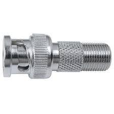
1 - The standard connector in CCTV is the BNC connector, which is the connector found on rear panels of cameras and DVRs.
So, if default connection is BNC, then use BNC connectors only! Never use F connectors with an BNC to F adapter.
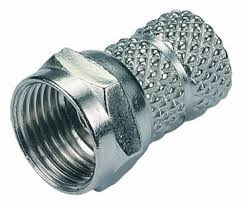
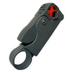
F connectors are for RF applications and has some models , such as the photo below, which are simply twisted around the cable mesh - preferred because they are easy to install. And to give poor contact also .
This type of connection should not be used under any circumstances.
2 - Types of BNC connectors
We can divide them into two groups:
Models that not require special pliers for the assembly
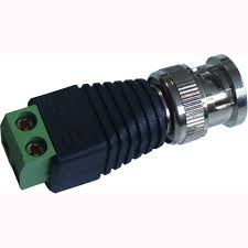
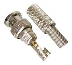
- BNC connector with terminals
For bench testing, with just a few meters of cable, it's OK. But it should never be used in an installation.
- Screw type BNC
Same considerations as of previous item.
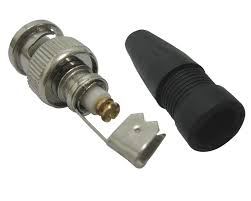
-BNC welding
This is not so bad. If welding is done well, it can be used . But it is not practical because it requires welding on site, sometimes in an open, windy, site, which hampers a solder well made. Therefore, it is very common to poor contact with cold weld in this type of connector. It should also not be used, mainly outdoor.
It can be said that above connectors are for consumer applications, for rapid testing . Not suitable for professional applications, for permanent premises in the works.
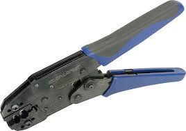
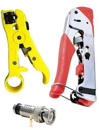
Models that require special pliers for the assembly
They are more expensive than previous connectors and require special pliers and some skill in their assembly, because any error disables the connector since it can not be reused .
However, the investment is worth the shame because, when properly applied, rarely have poor contact . They are the most suitable for professional applications.
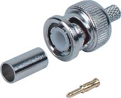
- Crimp connector
For their cost / benefit, they are the most currently used . They presents a good result, but requires a lot of skill in their assembly. It is the champion of poor contact in the works, as if mesh is unsuccessful pressed, cable easily escapes from the connector.
- Compression connector
It is the latest, the most expensive of all, and my favorite. It presents a very strong connection and does not require much skill in the assembly. That's what I recommend .
As assembly uses to work at first try, loss of connectors is smaller wich compensates its higher cost.
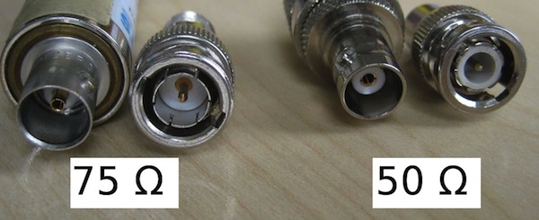
Always check connector's impedance!
Not only coaxial cables must have an impedance of 75 ohm, connectors also!
Unfortunately, no one pays attention to it and ends up using 50 ohm connectors with 75 ohm cables. But the difference is clearly visible: 50 ohm connectors have the dielectric (the white part) thicker. See below:
Worst of all, they fit perfectly together. And ignorance of this difference is so great that I found a very good quality professional camera, manufactured in South Korea, with a 50 ohm BNC connector:
.jpg)
When buying BNC connectors, always check if they are 75 ohms.
A final recommendation is that one should always choose the BNC connector with the proper dimensions for each cable. For example , you can not mount a BNC connector for RG -59 cable into a RG- 6 or RG- 11 cable; cable will not fit the connector.
The opposite is also true: an RG -59 cable mounted in a connector for RG- 6 or RG -11 will take off, giving poor contact .
So to grab the right connector to the right cable, always check the specifications of manufacturers.
Pliers for stripping, crimping or compression should also be suitable for the type of cable / connector used.
Conclusion
Connections between coaxial cables and BNC connectors are the simplest and more reliable because there is only one coaxial cable with two BNC connectors connecting a camera to a DVR / monitor.
Thus, whenever infrastructure and distances involved permits, prefer to use coaxial cable with compression connectors.
But do not be afraid of well test connections, making sure they are secure. When in doubt, redo them . Rather than being called later to fix what was done poorly ...
And remember that even if you are using another type of cable with converters (UTP or fiber, for example), you still have BNC connections in cameras and DVRs.
Part 4 - UTP Cabling ( soon)
Feb/2015
Jan 2016
Wanna know when new articles will be published?
Like this article? Leave a comment!
Copyright ©2014 CCTV Institute- All rights reserved
Total or partial reproduction of any content in this website is forbidden except if expressly authorized by the author